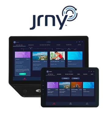
C7 Bike Assembly Video

Video Transcript:

Bowflex C7 Bike Assembly Video

Introducing the new Bowflex C7 bike.

Begin by selecting an area where you are going to set up and operate your bike. For safe operation the machine must be located on a hard level surface. Please allow a minimum work area of 24 inches around the perimeter of the bike. Be sure that the workout space you choose has adequate height clearance taking into consideration the height of the user and maximum incline of the fitness bike before you begin the assembly.

Please make sure you read the assembly manual thoroughly as it contains important safety warnings and assembly tips. Please note that there are some steps in the assembly process that might require two people to help with the assembly. Some components of the machine can be heavybor unwieldy. Please use a second person when doing assembly involving these parts. For assembly assistance please visit us online or give us a call. Check the assembly manual for a complete parts list.

Please note that a right r and left l decal has been applied to some parts to assist with assembly. The following wrenches are included with your assembly: a four millimeter allen key, a six millimeter allen key with a number two screwdriver and a combination 15 millimeter and 17 millimeter wrench. A cutting knife or scissors are recommended for this assembly.

Step 1: Attaching the stabilizers to the frame.

it is recommended someone assist you with this step. Begin step 1 by locating the front stabilizer, part 2 and setting it in front of the frame. If a tube is pre-installed in the stabilizer bracket, remove and safely discard. The stabilizer has pre-installed hardware that will have to be removed using the provided six millimeter allen key. Remove the top screws. Repeat these steps and remove all remaining hardware from the stabilizer.

Next, with some assistance tilt the frame and insert the stabilizer in front of the frame. Once the stabilizer is in place, secure it to the frame using the previously removed hardware. The hardware should be installed into the same holes of the stabilizer that they were previously removed from. Start by hand tightening the screws first, then fully tighten the screws using the provided six millimeter allen key. Once all hardware is tightly secured, proceed to locating the back of the frame. Locate the rear stabilizer part 3 and place it by the bottom back of the frame. The rear stabilizer has pre-installed hardware that will have to be removed using the provided six millimeter allen key. Remove the top screws. Repeat these steps and remove all remaining hardware from the rear stabilizer.

Next, with some assistance tilt the frame and insert the rear stabilizer in place. Once the stabilizer is in place, secure it to the frame using the previously removed hardware. The hardware should be installed into the same holes of the rear stabilizer that they were previously removed from. Start by hand tightening both screws first then fully tighten the screws using the provided six millimeter allen key.

Finally, using scissors or a knife, cut the indicated zip ties and remove any packaging material under the flywheel. Safely discard the material. Step one is now complete.

Step 2: Installing the handlebar post and seat post.

Begin step 2 by locating the seat post part 5 and placing it on the top of the frame tube on the location shown. The seat post is adjustable and it has multiple height locations written on the side. Slowly slide the seat post into place but take care not to set the seat post position higher than the stop mark on the tube. Hold the adjustment knob to adjust the seat post. Check an appropriate height for your seat system by sliding it up and down and then lock it into place by releasing the knob. Tighten the knob securely.

Next, locate the handlebar post part 4 and place it on top of the front frame tube as shown. The handlebar post is adjustable and it can be adjusted up and down. Slowly slide the handlebar post into place but take care not to set the handlebar post position higher than the stop mark on the tube. To secure the handlebar post, locate the handle part c and insert it into the front hole of the frame tube. Choose an appropriate height for your handlebar post by sliding it up and down and then lock it into place insert the handle. Fully tighten and make sure the handle points downward. To adjust the height after the handle is tightened, loosen the handle as you hold the handlebar post to prevent it from dropping. Move it to the desired position and tighten the handle. Pull the handle out to disengage and turn the handle so it points down then release.

Next, locate the seat assembly part six and insert it on the open end of the seat post, part five. Slowly push and slide the seat assembly into place. To fully secure the seat assembly, locate the adjustment handle part a and the flat washer part b, and insert them underneath the seat assembly. The seat position is adjustable and can be adjusted to a desired position after the handle is tightened. To adjust the seat after the handle is tightened, loosen the handle move the seat to the desired position and tighten the handle. Pull the handle straight down to disengage and turn it so it points rearward then release. When fully tightened, the adjustment handle must point rearward. Step two is now complete.

Step three: Attaching the pedals.

Begin step three by placing the left pedal part 7 on the bottom left side of the frame. Be sure to attach the pedals on the proper side of the bike. Orientation is based from a seated position on the bike. The left pedal and the crank arm have an L engraved on them while the right pedal and the crank arm have an R engraved on them. Before installing the pedal, there might be a little bag on the end of the crank to help keep the crank grease in place. Pull the bag off to expose the grease on the threads. Please note that the left pedal is reverse threaded so in order to tighten the pedal you must rotate it counterclockwise. When installing the pedals, it is very important that the pedal is installed straight into the crank arms by hand. If the pedals aren't installed straight, the threads that secure the pedals may strip. If you feel resistance and the pedal does not turn smoothly into the crank arm, then you may remove the pedal and start again to ensure that the pedal is aligned correctly. Try again and tighten the pedal by hand until you are sure that the pedal is going on straight into the crank arm. After several hand turns, fully tighten the pedal using the 15 millimeter wrench. Keep the pedal aligned as you fully tighten it with the wrench. Once the left pedal is secured, repeat these steps for the opposite side and attach the right pedal. The right pedal part 8 will have an R engraved on it. To attach the pedal, rotate the pedal clockwise. Keep the pedal centered and aligned while attaching it. After several hand turns, fully tighten the pedal using the 15 millimeter wrench. Step 3 is now complete.

Step 4: Attaching the handlebar assembly.

Begin step 4 by locating the handlebar assembly part 9 and placing it on the front of the frame as shown. The handlebar assembly is adjustable and the handlebar post has multiple length locations written on the side. Slowly slide the handlebar assembly onto the handlebar post. Choose an appropriate length reach for your handlebar.

Next, locate the part a and the flat washer part b and place them underneath the handlebar and handlebar post as shown. Insert the handle and washer through the handlebar post and into the handlebar assembly. To adjust the handlebar after the handle is tightened, loosen the handle. Move the handlebar to the desired position and tighten the handle. Pull to disengage and turn so it points forward, then release. Once the handlebar assembly is tightly secured, step 4 is now complete.

Step 5: Attaching the water bottle holders.

Begin step 5 by locating the water bottle bracket part 10. Next, locate the pre-installed hardware on the right side of the water bottle bracket. Remove the hardware using a four millimeter allen key and set the hardware aside for now. Repeat these steps for the opposite side.

Next, place the water bottle holder part 11 onto the bracket slowly. Move the holder in place and match the holes on the side of the bracket to fully secure the water bottle holder. Take the previously removed hardware and insert the screws through the holder into the bracket. Tighten the screws using the provided four millimeter allen key.

Next, repeat these steps for the opposite side and attach the second water bottle holder part 11 as previously shown. Fully tighten all hardware.

Next, place the water bottle bracket part 10 onto the handlebar assembly prior to attaching the bracket. You must remove the hardware from the handlebar assembly. The hardware is pre-installed on the top side of the handlebar assembly. Remove the hardware using the number two phillips screwdriver. Remove all hardware and set them aside for now. Slowly move the bracket in place and match the holes on the handlebar assembly. To fully secure the water bottle bracket, take the previously removed hardware and insert the screws through the bracket into the handlebar post. Tighten the screws using the number two phillips screwdriver. Step 5 is now complete.

Step 6: Attaching the console to the adjustable console mast.

Begin step 6 by locating the console part 14. Next, locate the back of the console and remove the pre-installed hardware. Remove the hardware using a number 2 phillips screwdriver. Once the hardware is removed, locate the adjustable console mast part 13 and route the console cable part 14a through the opening at the top. Route the cable through the tube and take care not to crimp the cables matching the holes to the mass plate. Push the console into place. Secure the console using the previously removed hardware. Fully tighten the screws using the provided number two phillips screwdriver. Tighten all hardware and take care not to over tighten the screws. Step six is now complete.

Step 7: Installing the console mast assembly.

Begin step 7 by removing the hardware located in the back of the handlebar assembly. Remove the pre-installed hardware using the provided 6 millimeter allen key. Set the hardware aside for now. Once all hardware is removed, attach the adjustable console mast to the handlebar assembly. Before attaching the console mast, verify that the cable 14a is oriented correctly as shown. With some assistance, push it into place and match the holes on the mast to the bolt hole locations on the handlebar assembly. Hold the console mast in place and fully secure it using the previously removed hardware. Tighten the screws using the provided six millimeter allen key.

Next, connect the console cable to the data cable part 1a and take care not to crimp the cables. Make sure to properly snap the connections together. When done properly, the cables should fit easily without much resistance. Once connected, push the cables down using the provided zip ties attach the cables so that they stay clear of any moving parts. Make sure to allow enough slack on the cable for the handlebar adjustment.

Next, locate the console junction shroud part 15 and place it behind the console on top of the adjustable console mast. Slowly slide down the shroud until it is fully inserted down the console mast. Make sure the console and console mast are straight before continuing. Step 7 is now complete.

Step 8: Attaching the ac adapter.

Begin step 8 by placing the ac adapter part 16 on front of the frame near the bottom of the frame assembly. The ac adapter comes in two pieces that need to be connected together. Before plugging in the adapter, connect both pieces together.

Next, slowly push the ac adapter into location and make sure that the power adapter wire stays clear of all moving parts. After connecting the ac adapter you may now proceed and attach the provided dumbbells part 17. Slowly place the dumbbells onto the dumbbell holders.

Congratulations, you have now completed the assembly of the Bowflex C7 bike.

Before using the bike, please make a final inspection. You may now remove any protective covers from the face of the console. Please inspect the bike to ensure that all fasteners are tight and components are properly assembled. Check pedals weekly to ensure they are tight. Do not use until the bike has been fully assembled and inspected for correct performance in accordance with the assembly manual. Please reference the assembly manual for workouts, troubleshooting and other program features.

Enjoy your new Bowflex C7 bike, brought to you by Bowflex.