

Treadmill 18 / Treadmill 7 Assembly Video
Below assembly video applies to both the Treadmill 18 and the Treadmill 7 machines.
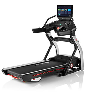
BowFlex Treadmill 7 Assembly Video
In this video we will show you how to install the bowflex treadmill 7 fitness machine.
Begin by selecting an area where you are going to set up and operate your treadmill.
For safe operation the machine must be located on a hard level surface.
Please allow a minimum work area of 77.9 inches and 163.6 inches.
Be sure that the workout space you chose has adequate height clearance taking into consideration the height of the user and the maximum incline of the machine.
Do not cut the shipping strap on the base assembly until it has been placed face up in the appropriate workspace before you begin the assembly.
Please make sure you read the assembly manual thoroughly as it contains important safety warnings and assembly tips.
Please note there are some steps in the assembly process that might require two people to help with the assembly some components of the machine can be heavy or unwieldly.
Please use a second person when doing assembly involving these parts.
Start the assembly by checking the parts list a right r and left ld cal have been applied to the parts to assist with assembly.
The following tools are required for assembly.
A number two screwdriver and six millimeter allen wrench are included with your assembly.
Step 1: connecting the input output cables and attaching the uprights
Begin step 1 by locating the base assembly part 14 and setting it flat on the floor next locate the right upright part 12 and place it on the front right side of the base assembly.
Slide the upright into place and match the holes located on the base upright insert two part a screws with two part c lock washers and two part d flat washers on the top of the upright mount.
Hold the upright in place and hand tighten the hardware at this time as you will need to fully tighten the hardware at a later step.
Insert two part b screws with two part c lock washers and two part d flat washers on the side of the upright mount. Repeat these steps for the opposite side and attach the left upright part 15.
Hand tighten the hardware at this time once both uprights are in place connect the console cables from the base assembly to the right upright cables. Be sure to fully connect the cable connectors. The connector should easily connect when inserted correctly. do not crimp the cables. Step one is now complete.
Step two: attaching the crossbar
Begin step 2 by locating the crossbar part 11 and placing it in between both uprights alright our decal has been applied to the right side of the crossbar to assist with assembly matching the inner holes of the uprights.
Slowly slide the crossbar into place next attach the right side of the crossbar using two part a screws two part c lock washers and two part d flat washers. Hand tighten the hardware at this time as you will need to fully tighten the hardware at a later step.
Repeat these steps for the opposite side. Step 2 is now complete.
Step 3: attaching the lower junction covers
Begin step 3 by locating the left lower junction cover part 5 and placing it on top of the left upright. Slowly slide it down into place repeat these steps on the opposite side and attach the right lower junction cover part 8.
Slowly slide it into place and take care not to let the console cables fall into the right upright. Step 3 is now complete.
Step 4: connecting the cables and attaching the console assembly
It is recommended that someone assist you with this step begin step 4 by locating the console assembly part 1 and holding it above the uprights. The cables from the right upright will be attached to the cables located on the right side of the console base assembly with some assistance hold the assembly while you connect the cables.
Be sure to fully connect the cable connectors the connectors should easily connect when inserted correctly once the cables are attached lower the assembly into place and take care not to crimp the cables.
Once the console is in place proceed to securing the assembly to the uprights using two part a screws two part c lock washers and two part d flat washers on the side of the upright mount and two part a screws two part c lock washers and two part e curved washers on the back of the upright mount.
Hand tighten the hardware at this time as you will need to fully tighten the hardware at a later step repeat these steps for the opposite side. Step four is now complete.
Step 5: tightening all hardware from the previous steps
Once both upright supports are attached go, back and fully tighten all hardware from the previous steps starting with the top console assembly hardware. Use the provided six millimeter allen wrench and fully tighten the hardware on both uprights.
Repeat this step for the opposite side and fully tighten all hardware using the provided six millimeter allen wrench. Next proceed to fully tighten the crossbar hardware using the provided six millimeter allen wrench. Finally fully tighten the hardware located on the bottom of each upright once all hardware has been tightly secured. Step 5 is now complete.
Step 6: attaching the side handlebars
Begin step 6 by locating the handlebar assemblies and the junction cover end caps a right r and left l decal has been applied to these parts to assist with assembly.
First slide the junction cover and caps into the handlebars, then slowly slide the handlebars into both the left and right uprights. Next attach each handlebar using four part a screws four part c lock washers two part d flat washers and two part e curved washers. Note that the curved washers are used on the bottom of each handle and the flat washers are used on the sides.
Insert two screws lock washers and flat washers through the side of the handlebar and hand tighten. Insert two screws lock washers and curved washers through the bottom of the handlebar. Fully tighten the screws using the provided six millimeter allen wrench repeat these steps for the opposite side. Step 6 is now complete.
Step 7: attaching the upper and lower junction covers
Begin step 7 by rising up the lower junction covers all the way to the top of the side rails. Next push the junction cover end caps up against the lower covers this will hold the lower covers in place. Locate the upper junction covers part 9 and part 2 and slowly insert into place attach the lower junction cover to the upper cover using two part f screws.
Insert the screws through the allocated bottom holes fully tighten the screws using the provided six millimeter allen wrench. Repeat this step for the left upper junction cover part two. Step seven is now complete.
Step 8: attaching the crossbar tray
Begin by locating the crossbar tray part 10 and placing it in front of the crossbar in between both uprights slowly lower the tray into place and fully cover the crossbar. Step 8 is now complete.
Step 9: attaching the base shrouds
Begin step 12 by locating the left base route part 16 and place it in between the upright and the frame assembly slowly lower it into place covering the bottom hardware. Next secure the shroud using one part g screw. Insert the screw through the shroud and fully tighten the screw using the provided phillips screwdriver.
Repeat these steps for the opposite side and attach the right base route part 13. push the cover into place and do not crimp the cables. Make sure the console cables are pushed down. Fully secure the base shroud. Step 9 is now complete.
Step 10: connecting the power cord and safety key
Begin step 10 by placing the safety key part 18 on the inside of the treadmill and inserting it into place. The safety key gets inserted to the center of the frame assembly as shown connect the safety key.
Next place the power cord part 17 in front of the treadmill near the bottom of the base assembly finally slowly plug in the power cord into location. Connect this machine to a properly grounded outlet only please see the grounding instructions in this machine when ready to operate the machine be sure to turn on the power with the power switch. Make sure that the power adapter wire stays clear of all moving parts.
Congratulations you have now completed the assembly of the treadmill 7. Before using the treadmill please make a final inspection you can now remove any protective covers from the face of the console as well as the plastic scratch guard strips from the rails. Please inspect the machine to ensure that all fasteners are tight and components are properly assembled do not use until the machine has been fully assembled and inspected for correct performance in accordance with the assembly manual. Please reference the assembly manual for workouts troubleshooting and other program features.
Enjoy your new Treadmill 7 brought to you by BowFlex.