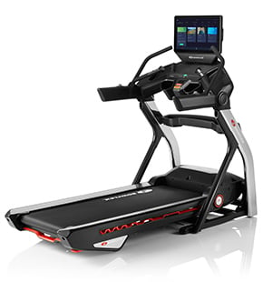
BXT6 Assembly Video
Bowflex BXT6 Treadmill Assembly
Start the assembly by checking the parts list. The following parts are required for installation. The following parts are included with your assembly. Check the assembly for the following hardware and tools shown on the hardware card. Select pieces of hardware may have been provided as spares.
Before you begin the assembly, please make sure to read the assembly manual thoroughly as it contains important safety warnings and assembly tips.
Begin by selecting an area where you are going to set up and operate your treadmill. For safe operation, the treadmill must be located on a hard level surface. Please allow a minimum workout area of 86 inches and 157 inches as shown. Be sure that the workout space you choose has adequate height clearance taking into consideration the height of the user and the maximum incline of the machine.
Step 1: Folding the walking deck.
For this step you will require the following parts.
Begin step 1 by placing the base assembly item number 14 face up as shown in the appropriate workspace. Cut the shipping strap on the base assembly. Please make sure that there is safe clearance around on and above your treadmill using the support bar found below the rear walking belt. Lift the walking deck fully upward and engage the hydraulic lift. Be sure that the hydraulic lift is correctly locked in place and that the locking mechanism is engaged. Carefully pull back on the walking deck and make sure that it does not move. When you do this, please keep clear of movement path in case the treadmill lock is not engaged. Caution: do not lean against the treadmill when it is folded. Step one is now complete.
Step 2: Attaching the uprights.
For this step, you will require the following parts.
With the base assembly still folded, attach the right upright item number 12 onto the bottom frame. Before attaching, connect the input output cables. Attach upright and taking care not to crimp the cables.
Next, hand tighten the two socket head screws including one lock washer and two flat washer each on each side of the upright. Attach the top using two socket hex head screws with one lock washer and one flat washer each on the location shown. Do not fully tighten hardware until instructed to do so later at step 7. Proceed by placing the left upright item number 15 on the opposite side by attaching the same hardware and repeating these same steps. Step two is now complete.
Step 3: Unfolding the walking deck.
Slightly push the walking deck forward toward the front of the treadmill with your left foot. Lightly push the top part of the hydraulic lift forward until the locking tube releases and you can pull the walking deck slightly toward the rear. Hold onto the walking deck until it moves approximately two-thirds down. The walking deck can possibly drop quickly in the last part of the movement, please make sure to keep clear off the movement of the walking deck. Step 3 is now complete.
Step 4: Attaching the crossbar.
For this step you will require the following parts.
Begin by placing the crossbar item number 11 between both the left and right uprights. A right R decal has been applied to the right side of this part to assist with assembly.
Next, attach the crossbar using two socket hex head screws with one lock washer and one flat washer each on the location shown. Hand tighten the screws. Do not fully tighten hardware until later instructed. Repeat steps for the opposite side. Step 4 is now complete.
Step 5: Placing the lower junction covers onto the uprights.
For this step you will require the following parts.
Begin by placing the right lower junction cover item number eight on top of the right upright. Do not let the console cables fall into the right upright.
Next, insert the left lower junction cover item number five on the top of the left upright. Slide the junction cover on and let it sit freely. Step 5 is now complete.
Step 6: console assembly.
For this step you will require the following parts.
Begin step 6 by placing the console assembly on top of the uprights and holding it in position. Connect the input output cables sticking out of the right upright. Please make sure not to crimp the cables while attaching the console. After attaching the cables, slide the console assembly into the uprights matching the holes on the side next. Secure the console using two socket hex head screws with one lock washer and one flat washer each. Hand tighten the screws on the side of the upright secure the front of the console using tube socket head screw with one lock washer and one curved washer. Do not fully tighten hardware until later instructed. Repeat these steps for the opposite side. Step six is now complete.
Step 7: Folding the walking deck.
In this step we will tighten all hardware from previous steps.
Begin by using the provided six millimeter allen wrench tool to fully tighten the top console hardware on both sides of the uprights. Repeat these steps for the opposite side.
Next, fold the walking deck up again as it is shown on step one and proceed to fully tighten the bottom hardware from previous steps. Repeat these steps for the opposite side. Step 7 is now complete.
Step 8: Attaching the base shrouds.
For this step you will require the following parts.
Begin step 8 by placing the right base shroud item number 13 on the bottom between the base assembly and the right upright. Attach the base shroud using one pan head phillips screw item f and one flat washer item g. Tighten the screw using the provided phillips head screwdriver.
Next, attach the left base shroud item number 16 on the left side and repeat the same steps.
Finally, unfold the walking deck after the base shrouds have been attached to the frame assembly. Step 8 is now complete.
Step 9: Attaching the side handlebars.
For this step you will require the following parts.
Begin by placing the left and right handlebar assemblies through the junction cover end caps. To assist with assembly, a visible mark R has been applied to the right parts and a mark L for the left parts after securing the end caps. Slide the handlebars into the frame assembly. Attach the handlebars using two socket hex head screws with one lock washer and one flat washer each. Tighten the screws on the side of the frame assembly using the provided six millimeter allen wrench.
Next, locate the bottom of the handlebar and secure to the frame assembly using one socket head screw with one lock washer and one curved washer as shown.
Next, secure the end caps to the handlebars using two panhead phillips screws with one flat washer. Each use the provided phillips head screwdriver to tighten both screws. Repeat these steps to the opposite side to secure the left handle bar. Step 9 is now complete.
Step 10: Attaching the junction covers.
For this step you will require the following parts.
Begin by sliding up the lower junction covers below the console assembly.
Next, snap the junction covers into place. A mark R has been applied to the right part and a mark L to the left part to assist with assembling. Secure each junction cover with two pan head phillips screws. Tighten each screw using the provided phillips head screwdriver. Repeat these steps for the opposite side. Step 10 is now complete.
Step 11: Attaching the crossbar tray.
Place the tray item number 10 between the left and right uprights and on top of the crossbar. Make sure tray is stable and centered. Step 11 is now complete.
Step 12: Connecting the power cord and safety key.
For this step you will require the following parts.
Begin step 12 by connecting the power cord on the bottom front of the machine. The power cord must be connected to properly grounded outlets only. When ready to operate, the treadmill be sure to turn on the power with the power switch.
Next, insert the safety key into the console assembly and clip onto the side.
Congratulations! Assembly of the Bowflex BXT6 is now complete.
Before using the treadmill, please make a final inspection. Please inspect the treadmill to ensure that all fasteners are tight and components are properly assembled. You can now remove any protective covers from the face of the console. Do not use until the treadmill has been fully assembled and inspected for correct performance in accordance with the owner's manual.
Enjoy your new Bowflex BXT6 treadmill, brought to you by Bowflex.


